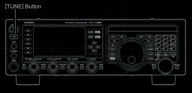
2. Press the [TUNE] button momentarily to place the ATU in the transmit line (no adjustment/tuning will occur yet). The "TUNER" icon will appear in the display
QUICK POINT:
3. Press and hold in the [TUNE] button for one second to begin automatic tuning. The transmitter will be engaged, and the "TUNER" icon will blink while tuning is in progress. When the optimum tuning point has been reached, the radio will return to receive, and the "TUNER" icon will again glow steadily (instead of blinking).
4. To disconnect the ATU from the transmit line, press the [TUNE] button momentarily. The "TUNER" icon will turn off, confirming that the ATU has been turned off. In the "Off" mode, the transceiver will be directly connected to the coaxial cable connected to your antenna, and will respond to whatever impedance is present at the station end of the coax.
ADVICE:
The momentary press of the [TUNE] button will turn the tuner on, and the microprocessor will automatically
select the tuning point closest to the current operating frequency.
The ATU circuit is located between the final aplifier and the rear-panel antenna jack; reception is not affected by the ATU.

QUICK POINTS:
As shipped from the factory, only one ATU alignment is saved on each Amateur band. This was memorized during the final alignment and performance verifications stages on the production line.
NOTE:
TERMINOLGY:
Please check the operating freqency before beginning the tuning process, to be sure you are not interfering with others who may already be using the frequency.
Antenna Tuner Memories: The microprocessor of the ATU makes a note of the selected tuning capacitors and inductors, and stores the data for each 10 kHz window for which tuning has occured. This eliminates the need to re-tune every time you return to a frequency on which you have already completed the tuning process.