FTDX1200 Operating Manual Page 129

INSTALLATION OF OPTIONAL ACCESSORIES Cont'd

Previous Page    Index of Topics    Table of Contents    Index of Pages    Next Page

RF µTUNE KIT

The RF µTuning Kits provide ultra-sharp RF selectivity for the front end of the transceiver. A very high Q tuned circuit makes possible the narrow-band design. Three RF µTuning Kits are available. The MTU-160 covers the 1.8 MHz band. The MTU-80/40 covers the 3.5 MHz and 7.0 MHz bands. The MTU-30/20 covers 10.1 and 14 MHz bands. The narrow bandwidth is especially useful on the low bands, when many strong signals are being received via NVIS propagation (Near Vetical-Incidence Signals) within a narrow bandwidth. The added protection for the receiver RF stages is especially helpful in preventing IMD and blocking.


Installation:
Assemble the RF µTuning Unit according to the "RF &midro;Tuning Kit Installation Manual" supplied with the RF µTuning Kit.


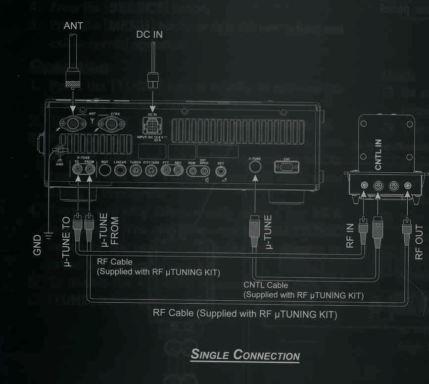
Interconnections to the FTDX1200:
Connect each cable (supplied with the RF µTuning Kit) between the RF µTuning Unit and the FTDX1200 transceiver.


ADVICE:

The RF connecting cables are color coded (black and gray) to assist in properly connecting the RF IN and RF OUT jacks (See illustration).

An improper connection will not damage the RF µTuning Kit. However, improper operation may occur.

Connect the color-coded control cable(s) betwen the CNTL OUT and CNTL IN jacks (See illustration). Confirm all connections before turning on the transceiver.

If the FTDX1200

The order of connecting multple RF µTuning Units is not important.


End of "RF µTune Kit Installation"


Cont'd Next Page "Installation of Optional Accessories"

Previous Page    Index of Topics    Table of Contents    Back to Top    Index of Pages    Next Page

FTDX1200 Operating Manual Page 129